I. Pre-Adjustment Preparation (Mandatory)
No-Load Inspection: Remove the welding torch and wire spool. Confirm that the arm rotates smoothly (vertically and horizontally) without binding or abnormal noise. Ensure joint locking bolts are slightly loosened to provide moderate damping.
Load Matching: Install a standard wire spool (with wire), the wire feeder, the torch, and all necessary cables to simulate actual working weight.
Tools & Safety: Prepare hex keys (Allen wrenches) and flat-head screwdrivers. Safety Warning: Clear the area directly beneath the arm to prevent injury in the event of an accidental drop.
Identify Adjustment Points: Locate the balance adjustment mechanism-typically a worm gear on a spring balancer (hex drive) or a tension spring adjustment bolt with a scale/ratchet lock.
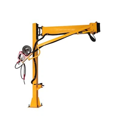
https://www.weldingboom.com/wire-feeder-arm/
II. Core Adjustment Procedure (Coarse → Fine → Full-Range Validation)
1. Coarse Adjustment (Weight Matching)
Locate the balancer adjustment worm gear (usually found at the base or side of the arm).
Clockwise (+ Tension): Increases spring tension to counteract the front-end load and prevent sagging.
Counter-Clockwise (- Tension): Decreases spring tension to prevent the arm from drifting upward.
Reference Standard: When the arm is held horizontally and released, it should remain stationary with no significant vertical drift.
2. Fine-Tuning (Achieving "Zero-Gravity" Hover)
Lower Range (-30° to 0°): If the arm tends to sink, turn the adjustment bolt clockwise in 1/4-turn increments until stabilized.
Mid-Range (0° to +30°): This is the critical horizontal zone. Fine-tune until the arm moves with a light touch and stays exactly where it is released.
Upper Range (+30° to +60°): If the arm "pops up" uncontrollably, slightly reduce tension (counter-clockwise).
Joint Damping: If horizontal rotation is too loose or too stiff, adjust the friction damper bolts on the pivot joints to ensure smooth rotation without inertial over-travel.
3. Full-Range Validation (Final Testing)
Slowly move the arm from the lowest to the highest point. Ensure it holds its position at any angle without drifting or jerking.
Rotate the arm horizontally. Resistance should be uniform across the entire arc, with no self-rotation after release.
Perform 5–10 full-motion cycles under full load (full spool + torch). Verify that the balance remains consistent and that no abnormal mechanical noises occur.